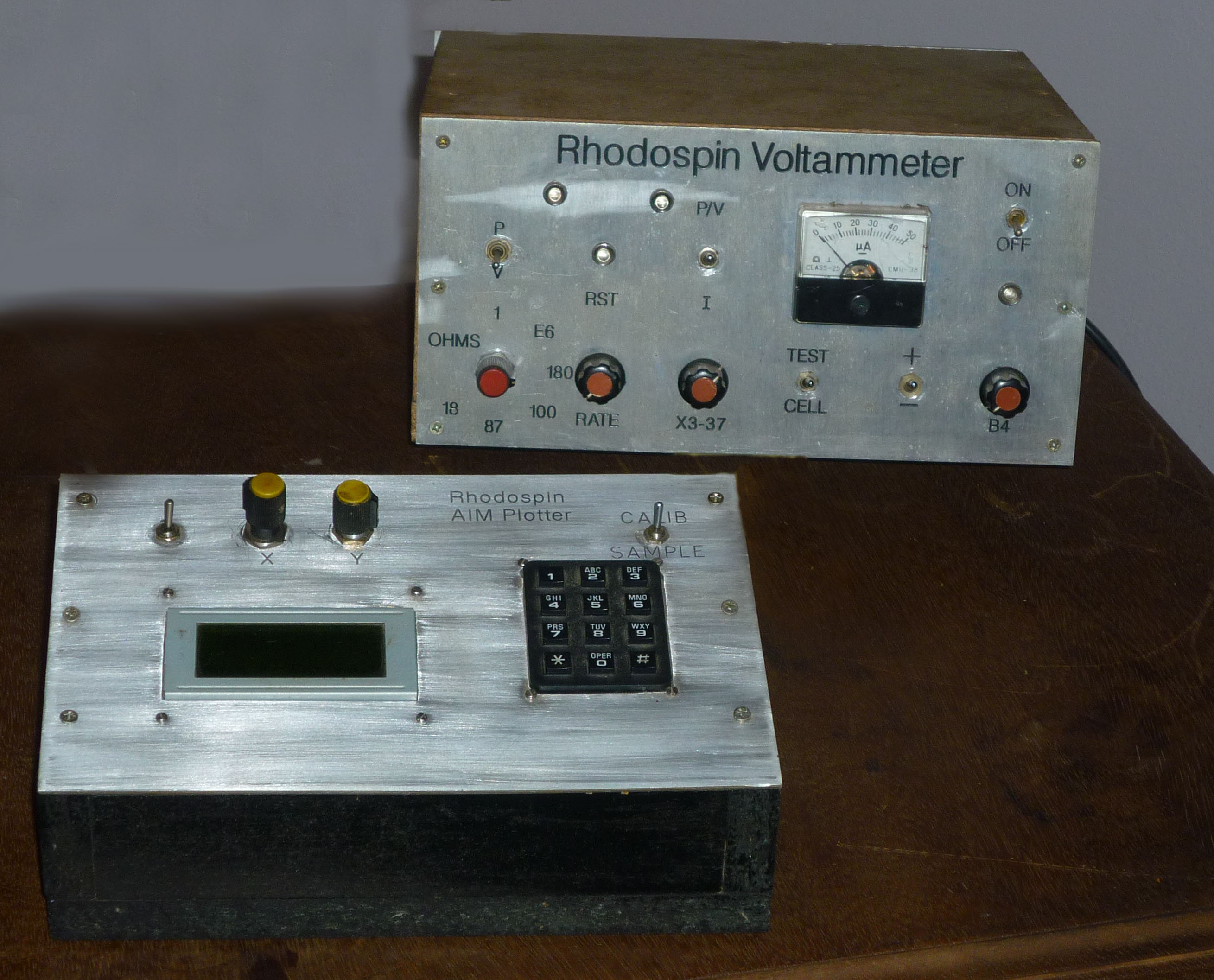
Voltammeter - Linear Scan Model
In the book entitled "How to make a Computer controlled Square Wave Voltammeter" previously called "Chemical Computers" listed at the bottom of this page you can download a detailed revision of electronic explanation and Visual Basic example. The USB6008 provides one digital analog convertor or DAC,two simultaneous analog digital convertors or ADC's,one digital output port P(0,0) and PFIO which captures the clock output of a 4046 Phase lock loop or PLL.
The USB6008 interfaces with the USB port of your PC and we use Visual Basic to control operations. Basically we have managed to achieve an SWV signal with a step height of 1 mVolt and a pulse at the origin of the step of 50mV.The DAC output can be 0.001V min to 5.000V max. and is programmed for the output in volts that you want to produce up to 5V in steps of 1mV.The ADC's are good for a pos rail of 10V and a neg rail of -10V. The Voltage readings are a simultaneous account of Voltage of the reference electrode and current related voltage of the current follower, following the current of the working electrode.
The Timer Tick event repeatedly has 50 added to number then it is converted to mV by /1000 then it is written to the DAC. In units of volts . Now Voltage is read,namely Vhi(resno) and ihi(resno) then 49 is subtracted from number ,/1000 and written to DAC .Then take a reading of voltage again namely Vlo(resno) and ilo(resno).Thats the loop and the power of software!The current at Vhi(resno) is ihi(resno)-ilo(resno).This is what is plotted as the Voltammogram. The peak with a Diode Test Cell is discernable from this Voltammogram but to remove some noise the average of four succesive points is taken as a point.

Chemical Computers - Free download below:
My Introduction
My Semi-Conducter Intelligence
My Electrochemistry